Nature Materials 6, 735 - 739 (2007)
Published online: 19 August 2007 | doi:10.1038/nmat1984
Subject Categories: Metals and alloys |Mechanical properties | Nanoscale materials
Tensile ductility and necking of metallic glass
H. Guo1, P. F. Yan1, Y. B. Wang1, J. Tan1, Z. F. Zhang1, M. L. Sui1* & E. Ma2
Abstract
Metallic glasses have a very high strength, hardness and elastic limit. However, they rarely show tensile ductility at room temperature and are considered quasi-brittle materials1, 2. Although these amorphous metals are capable of shear flow, severe plastic instability sets in at the onset of plastic deformation, which seems to be exclusively localized in extremely narrow shear bands  10 nm in thickness3, 4, 5, 6, 7, 8, 9, 10, 11, 12, 13. Using in situ tensile tests in a transmission electron microscope, we demonstrate radically different deformation behaviour for monolithic metallic-glass samples with dimensions of the order of 100 nm. Large tensile ductility in the range of 23–45% was observed, including significant uniform elongation and extensive necking or stable growth of the shear offset. This large plasticity in small-volume metallic-glass samples did not result from the branching/deflection of shear bands or nanocrystallization. These observations suggest that metallic glasses can plastically deform in a manner similar to their crystalline counterparts, via homogeneous and inhomogeneous flow without catastrophic failure. The sample-size effect discovered has implications for the application of metallic glasses in thin films and micro-devices, as well as for understanding the fundamental mechanical response of amorphous metals.
Introduction
In sharp contrast to crystalline metals that have large tensile ductility including significant uniform elongation, monolithic metallic glasses show little or no macroscopically observable tensile strain at room temperature1, 2, 3, 4, 5, 6, 7, 8, 9, 10, 11, 12, 13. Under compressive loading with or without confinement, plasticity is often observable, but is always highly inhomogeneous. The strains are concentrated in narrow shear bands that are not only few in number but also tend to run wild to cause early failure. It is thus believed that the vast majority of the metallic-glass sample volume does not contribute to plastic deformation1, and severe strain localization is the only deformation mode at temperatures well below the glass-transition temperature.
In the following, we demonstrate qualitatively different behaviour in small-volume metallic glasses. The behaviours common to ductile crystalline metals, including uniform elongation, necking and stable shear, can all happen when the sample dimensions of the metallic glasses are brought into the submicrometre to nanometre range. Hints for important changes in deformation modes have emerged recently in micrometre-sized samples14, 15, 16 (Z.W. Shan et al., unpublished). To observe the entire sequence of deformation stages in small samples, we carried out in situ tensile straining experiments in a transmission electron microscope (TEM) on several monolithic metallic-glass samples with dimensions in the 100 nm range.
The material studied was a typical bulk metallic glass, Zr52.5Cu17.9Al10Ni14.6Ti5, prepared using copper-mould casting10. This alloy was studied previously in conventional mechanical tests10: the total plastic strain to failure was 1% in compression and nearly zero in tension before fracture (the elastic strain was 1.7%). A slice with dimensions of 45 10-4 s-1. The sample design, testing schemes and electron-beam-heating effects are discussed in the Methods section.
Figure 1: Small-volume metallic-glass samples for thein situtensile straining experiment in the TEM.
a, A slice of metallic glass glued to a brass substrate for in situ tension. b,c, Viewing directions for the first (b) and second (c) steps of FIB micromachining of the samples at the edge of the metallic-glass slice. d, A schematic diagram of the three submicrometre samples prepared using FIB. e, SEM image of the 100-nm-thick platelet fabricated, viewed from the angle in b. f, SEM image of the sample columns tested and their surrounding platelets (the dimensions are given in the text) separating the samples; the sample gauges had dimensions of 100 nm250 nm.
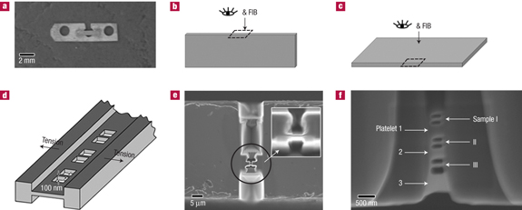
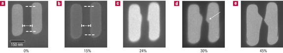
Figure 2 shows a series of video frames presenting the typical behaviour of sample I during the in situ tension experiment. Interestingly, measurements of the lengths of the gauge section (marked by dashed horizontal white lines) indicate that the sample uniformly elongated, up to a strain as high as 15% (Fig. 2b). This is the point when the first sign was observed for non-uniform deformation starting at a location slightly above the middle of the gauge section. One shear band was initiated, and the shear offset became obvious at the stage shown in Fig. 2c, where the total elongation reached 24%. This strain increment (from 15 to 24%) is partly a result of the slow growth of the shear offset, without the rapid fracture common in conventional metallic-glass test samples8, and also of the preferential thinning of the material in the middle (Fig. 2c). This necked region (marked with an arrow in Fig. 2d) narrowed gradually and considerably, also contributing elongations without fracture, as shown in Fig. 2d,e. At the stage shown in Fig. 2e, the total tensile strain reached 45% (if we discount the strains non-uniformly concentrated in the thin neck in the middle, the rest of the gauge section experienced an elongation of 29%). We emphasize that the large strain here was not achieved through the formation of multiple shear bands9, 10, 11, 12, 13, 18, 19, 20, 21, 22.
Figure 2: Sample I at various stages of tensile elongation during thein situTEM experiment.
The average strain rate was about 510-4 s-1. The straight gauge section is marked with dashed white lines. a–e, This series of video frames demonstrates that the virgin sample before testing (a) was uniformly elongated to a strain of 15% (b), where non-uniform deformation began; one major shear was initiated, and the shear offset grew with further straining together with significant elongation in the necked region indicated by the white arrow (c–e). The tensile strain for e reached 45%.
Samples II and III both had some unevenness on the sample (side) surfaces after FIB cutting. These ~notches~ in the virgin samples before testing served as stress concentrators and encouraged necking to start early during the in situ tensile straining experiments. Figure 3 shows a series of photos from the videotape, showing sample II at different straining stages. Necking was the dominant deformation mode (from Fig. 3b–e), starting from the pre-existing notch (marked with an arrow in Fig. 3a). The necked region had a very small volume, a complex stress state, and the aspect ratio was low resulting in confinement12, 13, such that continued 45° shear was not favoured23. In fact, throughout the test shear did not localize on one dominant plane. The necked region enlarged and spread out gradually, and the extensive necking led to an elongation to failure of 23% in Fig. 3e after recovering the elastic strain. It is well known that gradual necking only occurs in ductile metallic materials, and the area reduction ratio, 80%. Such extraordinary ductility has never been observed in metallic glasses; some signs of necking were occasionally observed only when large volume fractions of ductile crystalline dendrites were added into a glass to form metallic-glass composites9.
Figure 3: The necking process in sample II observed during thein situtensile testing in the TEM.
a–e, The ~notches~ on the surfaces in the virgin sample (indicated by the white arrow in a) encouraged necking to start early, developing extensively and gradually (b–e). The strain to failure at e reached 23%, and the area reduction ratio at fracture is as high as 80% (also see the close-up views in Fig. 4).
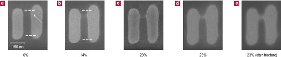
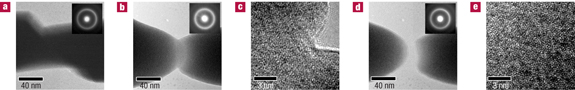
Figure 4: TEM bright-field images and corresponding electron diffraction patterns (insets) of thein situtested samples at various stages of straining.
a, Sample I at an elongation of about 24%. b, The necked region in sample II at an elongation of about 20%, before fracture. c, HRTEM image of the region shown in b. d, The eventually fractured region in sample II. e, The HRTEM image corresponding to d. All of the images and electron diffraction patterns confirm that no crystallization occurred throughout the experiment.
Sample III behaved in the same manner as sample II. In addition, see above for sample I for the large post-uniform deformation. To further check the reproducibility of the results, a separate batch consisting of two further samples was made and they both fractured with obvious necking. This suggests that the necking behaviour reported above is common for such small-volume bulk metallic glasses under tensile loading. The easy occurrence of the necking instability in tension is expected for a material such as monolithic metallic glass that does not possess an obvious mechanism for strain hardening1, 23. To reproduce the major shear reported for sample I in Fig. 2, we should suppress surface undulations (Fig. 3) that could accelerate early necking. This was difficult for the 100 nm samples using our current FIB cutting procedures. However, such behaviour should be easily captured in compression tests, in which the sample is not subject to the necking instability. Indeed, in situ TEM videos of several samples of a similar Zr–Cu–Al metallic glass in nanocompression tests showed nearly homogeneous deformation followed by slow, stable growth of the shear offset on a shear band after it is initiated (Z.W. Shan et al., unpublished).
The wider platelets surrounding samples I to III also offered the opportunity to observe the behaviour in Fig. 2. This is because necking is known to start at larger critical strains for the thin-plate geometry, and here the edge undulations also have smaller effects because they are minor compared with the platelet width. Indeed, homogeneous deformation also occurred in the three platelets up to an elongation of about 14%, followed by localized shear in various directions. These platelets also have dimensions in the submicrometre regime, such that the localized deformation was also stable. In fact, the wider platelets continued to deform without reaching final failure, after the three samples fractured one after another. Apparently the larger volumes of the platelets provided more room for accommodating the damage (localized strains).
Figure 4a shows a TEM bright-field image of sample I, taken at a tensile strain of about 24%. There is no change of contrast, which is consistent with the diffraction pattern in the inset indicating no induced crystallization even in the heavily deformed region. Figure 4b shows the TEM bright-field image of sample II after pronounced necking but before fracture. The inset electron diffraction pattern again shows that no crystallization occurred, which is further confirmed by the high-resolution TEM (HRTEM) image in Fig. 4c. Even after fracture, both the electron diffraction pattern (inset in Fig. 4d) and the HRTEM image in Fig. 4e indicate that crystallization was never induced in this heavily strained necked region. This is also true for other necked and fractured samples, as confirmed with post-fracture diffraction and dark-field examinations. These observations are consistent with a low deformation temperature in our test samples. The plasticity here comes entirely from the flow of the monolithic glass, very different from the deflection and branching of shear bands due to surrounding nanocrystals as suggested previously for the compressive plasticity observed in some metallic glasses8, 11, 24.
Homogeneous deformation of metallic glasses is known to occur only when the test temperature is elevated to above1, or at least close to, the glass-transition temperature (Tg=675 K for our glass). In that case large ductility is achieved owing to viscous flow, which commands a high strain-rate sensitivity leading to superplastic-like behaviour without necking. In the low-temperature regime, homogeneous deformation with uniform elongation, or non-uniform deformation via extensive necking, was predicted for extremely small wires in molecular dynamics simulations, which were only able to handle a diameter of 13.6 nm (ref. 23). Our findings indicate remarkable sample-size effects: the small volume delays catastrophic localization and increases failure resistance, leading to large tensile elongations.
Let us examine these effects from several angles. First, the sample dimension is now well below the normal range of the shear-band spacing (typically micrometres) observed in samples after conventional tests1, 11, 25, 26, 27. The small sample volume is less likely to contain flaws, or (pre-damaged) fertile sites, for the initiation of a severely localized shear band. There is also limited room for a major instability (a particular Fourier component) to grow to dominance out of the fluctuating shear events ongoing throughout the sample27. This reduces the probability of forming a predominant instability that pre-empts homogeneous deformation. Without severe shear banding that concentrates all of the strains exclusively on one plane, throughout the sample the individual shear-transformation zones (or their groups)28 and the local redistribution of free volume29 have the opportunity to mediate multiple atomic-level shear events. These ~dislocation-like~ shear events, happening all over the small volume, render elongations that seem homogeneous over a range of strains (Fig. 2). The results of compression tests of microscale or nanoscale metallic-glass samples14, 15, 16 (Z.W. Shan et al., unpublished) also support this observation. Note that the shear transformations, being thermally activated and stress-assisted processes, always have a finite chance to contribute to deformation at sufficiently high stresses1.
Second, even after localization begins, for example, with the presence of a minor notch that led to necking (Fig. 3) or after a major shear that eventually sets in (Fig. 2), in small-volume metallic glasses failure does not immediately ensue. This can be rationalized from several perspectives. The plastic zone size at the tip of an incipient crack<a href="http://www.>>>>></body></html>